New York New York USA
North America - Welcome to "Timeout for Tech with Gary T. Fry, Ph.D., P.E."
Each month, we examine a technology topic about which professionals in the railway industry have asked to learn
more.
This month our subject is wheel/rail contact and wheel load attenuation.
In North America, a steel wheel under a fully loaded rail car routinely supports 36,000 pounds of load.
As wheels roll over rails, the surfaces in direct contact flatten, much like pressing the tips of your fingers
together.
This deformation results in the formation of a "contact patch" between the wheel and rail that is roughly the
size of a U.S. dime, 0.4 square inches.
The average vertical pressure applied to the steel within the area of contact is roughly 90,000 PSI (pounds per square
inch).
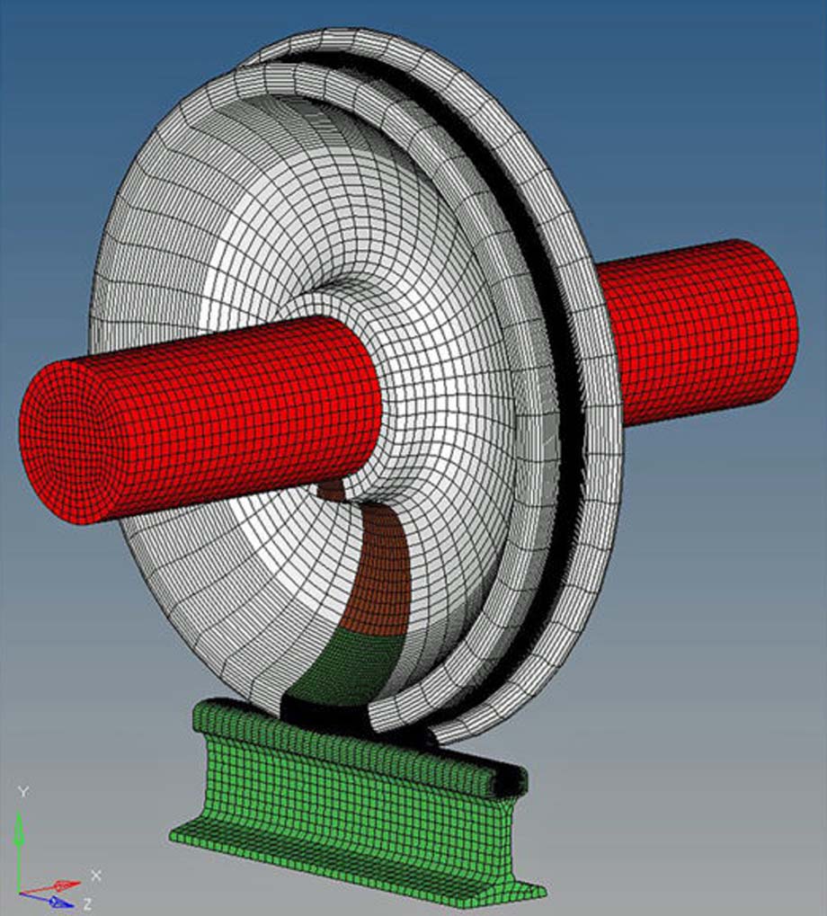
Figure 1 above shows a railway wheel in contact with a rail.
The very small contact patch under a heavy wheel load is one of the main reasons that trains are incredibly energy
efficient.
The resulting pressure in this small contact patch, and its repeated application as wheels roll along the rails,
present several interesting engineering challenges.
Before diving into those details, there are some other areas of contact visible in Figure 1 that we should consider:
rail/tie-plate, tie-plate/tie, and tie/ballast.
To begin, we must recognize that the rail acts as a beam distributing each wheel load among a few ties.
When a wheel is directly over a tie, we can estimate simply that the load is shared among the five nearest ties such
that a tie directly beneath the wheel receives 50 percent of the load.
As a result, the maximum force between each of the three contacting surfaces below the base of the rail at a given tie
location is close to 18,000 pounds.
The notional area of contact between the base of the rail and a tie plate is roughly 45 square inches giving an
estimated average vertical pressure of 400 PSI.
The notional area of contact between the tie plate and the timber tie is roughly 110 square inches, giving an estimated
average vertical pressure of 170 PSI.
Finally, the notional area of contact between one half of a timber tie and the ballast is roughly 460 square inches,
giving an estimated average vertical pressure of 40 PSI.
The important takeaway is this:
The average vertical pressure caused by a wheel load diminishes substantially at locations away from the immediate
vicinity of the wheel/rail contact patch.
And that is an essential purpose of the track structure, to attenuate wheel loads so that heavy trains can be supported
by the ballast and soil beneath.
Much more rigorous methods exist to model these pressures, but the takeaway is the same.
The average vertical wheel/rail contact pressure is roughly 2,000 times greater than the average vertical tie/ballast
pressure.
Let's return to the wheel/rail interface.
Steel is used as the material of choice for wheels and rails.
Specifically, among other attributes, steel alloys are chosen that are economical to produce in large volumesm=, and
are processed to be strong, resistant to forming fatigue defects, and resistant to abrasion and wear.
Especially over the past 40 years, the rail industry has made substantial progress in developing improved steel alloys
and extending the safe lifespan of wheels and rails.
But fatigue cracks that form in wheels and rails remain a common root cause for component replacements and train
accidents.
To help mitigate these undesirable outcomes and support development of improved materials, detailed computer models of
wheel/rail contact can help our understanding of fatigue defects in wheels and rails.
Figure 2 below is a rendering of such a model.

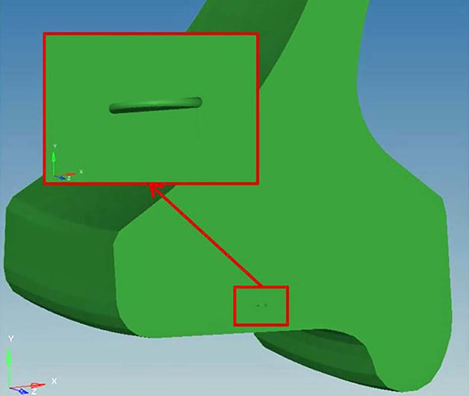
While not immediately apparent, this model includes a small, penny-shaped fatigue defect that the model
predicted forming at a highly stressed location in the wheel rim.
Figure 3 below shows a close-up view of the location of the defect.

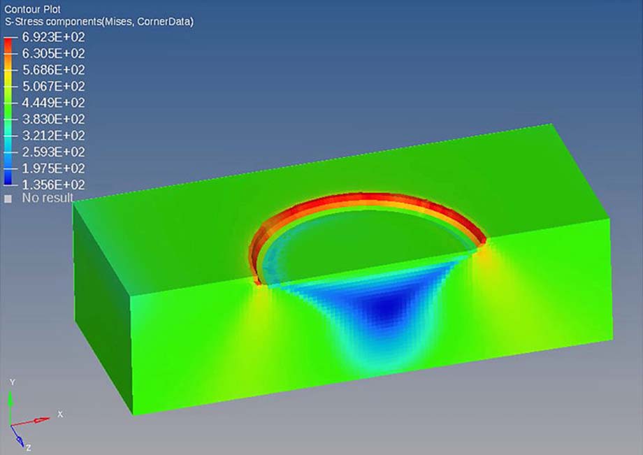
Figure 4 below shows a plot of the maximum stresses through a section of material surrounding the defect as the
wheel rolls on the rail.

Computational models like these provide several insights.
We can use them to determine the most likely locations of fatigue defect formation, the most likely orientations of the
defects, the growth rates of the defects, and the critical sizes of the defects that will result in component
failure.
All that information is essential to designing inspection and maintenance programs that simultaneously mitigate the
risk of component failure while optimizing component service life, utilization, and reliability.
These models can also help engineers design and evaluate new material systems and component details.
The goal is to identify essential characteristics that would represent improved performance for a material and/or
component.
Then the behavior of the material/component is simulated under loading conditions representative of its expected use in
service.
In the simulation environment, multiple candidate materials and components can be compared and ranked in terms of
expected performance and are essentially prescreened as promising for further development and prototype
testing.
Another role for computational modeling is designing and simulating the prototype testing.
Detailed models are becoming increasingly popular in this regard as a means of optimizing value and effectiveness of
testing programs and associated data collection and processing.
So, what does the future promise in terms of improved materials and component designs for railway wheels, rails,
tie-plates, and ties?
Two obvious objectives are increased defect-free service life and reduced maintenance under increased demands from
trains.
That means developing materials with increased capacities against fatigue and other forms of degradation and developing
components that offer reduced demand on their materials under load.
The future is bright if we continue to pursue the Five I's, Identify, Invest, Innovate, Implement, and
Improve!
Gary T. Fry.
(likely no image with original article)
(usually because it's been seen before)
provisions in Section 29 of the
Canadian Copyright Modernization Act.

