


ON THE SOUTHERN PACIFIC
The longest stretch of track operated under the electric train staff system in this country, covers 94.2 miles of single track on the Southern Pacific, between Loomis and Truckee, California. The road between these two points crosses the Sierra Nevada mountains at an elevation of 7,000 feet and a maximum grade of 2.7 percent. For 41 miles in the vicinity of the summit, where the snow last winter reached a depth of 27 feet, on the level, the tracks are covered with immense snowsheds, and night signal indications are displayed 24 hours each day.
The summit is 15 miles west of Truckee, which is the eastern staff terminus, and under normal traffic conditions it is necessary to cut out a number of helper engines here each day and return them light to the foot of the grade. These with the large number of transcontinental trains passing over this road overtaxed the line under the old system of train orders and telephone block to such an extent that traffic was constantly being delayed.
The staff system furnished by the Union Switch & Signal Company, was installed in 1905 and 1906, and has relieved the congestion by cutting down the delay at meeting points and enabling the dispatcher to keep the trains moving, as he can change a meeting point in about five seconds, whereas with the old system from three to ten minutes would be required. To change one meeting point would often necessitate changing several others. The 94.2 miles of single track covered by the installation is divided into 35 blocks, averaging 2.7 miles each. Two instruments, one placed at each end, are required for the control of each block, and these are connected by a metallic circuit, a three-conductor cable being used for this purpose through the snowshed district. This is supported by a No. 9 galvanized iron messenger wire tied to oak brackets on the inside wall of the snowsheds. This is dead-ended at each station, and carried to lightning arresters in the pedestal of each instrument by a No. 14 rubber covered copper wire along with the cable, so that it, as well as the extra strand in the cable, can be used in case of emergency.
Outside of the snowshed district two No. 6 galvanized iron wires are strung on poles set approximately 64 to the mile. This lead also carries telegraph and other wires.
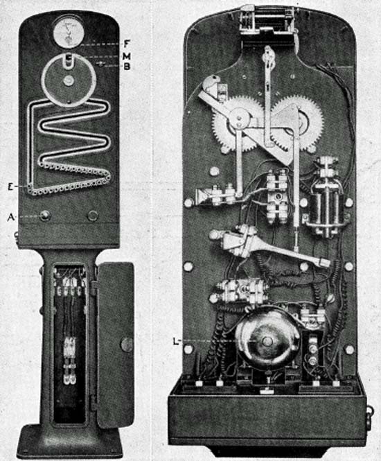
Figure 1 is a front view of one of the staff machines and Figure 2 is a rear view of the head with the cover removed showing the mechanism.
To withdraw a staff the operator at a station "A" presses button A in figure 1 three times, ringing the bell L in figure 2, at station "B", the opposite end of the block. The operator here, after consulting his block sheet, answers the signal and holds the button in, thus supplying current to the instrument at station "A", which is indicated to the operator there by the deflection of pointer F in figure 1. Station "A" now turns the spindle B to the right as far as it will go, and then allows it to return to its normal position. This has brought the armature up against the cores of the locking coils, where it is held. The red disc in the face of the instrument now disappears, indicating to station "A" that the unlocking has been accomplished. The circular shield has previously been brought into position for the slot to receive staff E, which is now brought into place and used to turn the shield to the position shown, and the staff is then withdrawn at M.
The act of removing the staff has operated the pole changer shown in Figure 2, putting the batteries of the two instruments out of synchronism, and no more staffs can be withdrawn until this one is put back in this instrument or the one at the opposite end of the block.
For delivery the staff is placed in a rubber pouch attached to a steel hoop of about 14 inches diameter and hung on the staff delivery crane. Figure 6 is a view of the crane. From it enginemen are able to catch the staff at speeds of 40 miles per hour or more. The crane consists principally of a counter-balanced arm, pivoted at the head of a mast, and carrying at one end a spring clasp shaped to receive the staff hoop, and from which it can he withdrawn with a slight pull. Figure 6 view shows a staff in position to be caught. When the arm is relieved of the weight of the staff the counter-balance brings it to an almost vertical position out of the way. At the approach to each station there are two signals of the enclosed disc type, home and distant, mounted on a pole and located 60 feet in the rear of a switch. By these the operator is able to give the following indications: (1) take siding, (2) continue along the main line prepared to stop at the office, and (3) continue along the main line, staff for the next block is in the crane.
A distant signal of the same type is placed approximately 1,500 feet in advance of the home signal, to regulate the approach thereto. The home signals are operated by from four to six cells of a storage battery placed at the station, the same battery operating signals on each side of the station. The distant signals require two cells of the same type which are placed at the signals. The storage batteries are all of the Exide portable type used extensively in the operation of automatic block signals on the Southern Pacific road, and in this service require charging but once every 30 days.
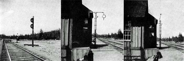
Figure 4 is a wiring plan for stations, showing how the signals and instruments are interconnected. The normal indication of the signal at a station is "take the siding", and this cannot be changed if the track between switches is occupied. The indication, "proceed to the office" is obtained by the operator moving the signal controller to the second position which clears the home signal at the switch and the distant signal proper, leaving the caution signal displayed at the switch. For the next indication all signals must be cleared. Before this can be done it is necessary for the operator to obtain a staff for the next block, use it to unlock the signal controller, move the controller to the third position, and place the staff in the crane for delivery. This last act closes the final break in the circuit, which is in a circuit breaker attached to the staff crane arm.
With this indication displayed a train would proceed at normal speed, the engineman dropping the staff he has at the station, and catching the one giving him the right to proceed through the next block.
To avoid the possibility of the operators placing the staff left by the train, in the instrument controlling the block into which it has just passed, the instruments are made in four styles known as "one", "two", "three", and "four". The staffs are stamped with these numbers, and a No. 1 staff cannot be placed in anything but a No. 1 machine, etc., so that a staff would have to be carried by three block stations before another machine of the same number would be reached.
At Summit station a special feature is attached to one of the instruments which was designed to protect helper engines while returning to the station after helping a train part way through the block. This consists of a box containing a staff of special design, differing very materially from the others, and plainly stamped "Pusher Staff" so there is no danger of confusing it with those conveying right to proceed through the block. The pusher staff cannot be withdrawn from the box until a staff for the block has been obtained and used as a key to release it. The regular staff may then be delivered to the train, and the pusher staff to the engine which is to cut loose at the top of the hill and return. Both engine and train will now be fully protected in the movements they are to make, by the fact that the withdrawal of the pusher staff opens the staff circuit, leaving the block completely locked up until it is returned to its place in the box, and the regular staff is placed back in one or the other of the instruments.
In the operation of the staff system here, regular trains starting out receive a clearance card, and extra trains receive a 19 order to "staff" Loomis to Truckee, or vice-versa. No other orders are necessary. Operators have instructions to "staff" the superior train first unless otherwise directed by the dispatcher. Twenty stations are telegraph offices, and 16 are only block stations, the signalmen at these receiving their instructions as to the handling of trains through the operator at the adjoining telegraph station by telephone. There is a telegraph office on at least one side of each telephone station.
The question of maintenance is taken care of by seven repairmen, whose districts average about 13 miles in length. Each repairman looks after everything on his district, and in addition, in the snowshed district, maintains a system of fire-alarm and district-telegraph boxes, which are used in the protection of the track and snowsheds in this territory.