Steering a train is something we have left to rails and flanges for years, but can electronics do better?
First, prepare yourself for a shock.
Some RSSB research cash has been used for some real hardware, I think this is the second time ever, and we have barely had time to get over the multi-shot sander.
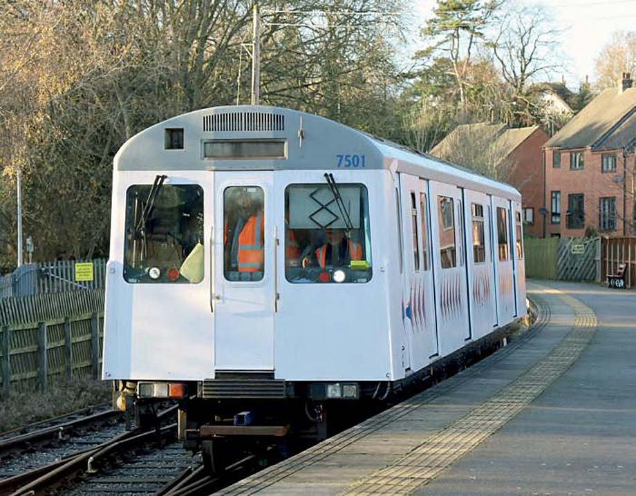
This cash has gone to SET Ltd to produce independent steering rail wheels, fitted to a Vivarail D stock battery vehicle and running up and down the Ecclesbourne Valley.
Entry Level Wheel-Rail Interface
Before I write something more impenetrable than one of Captain Deltic's signalling articles, let's brush up on the basics.
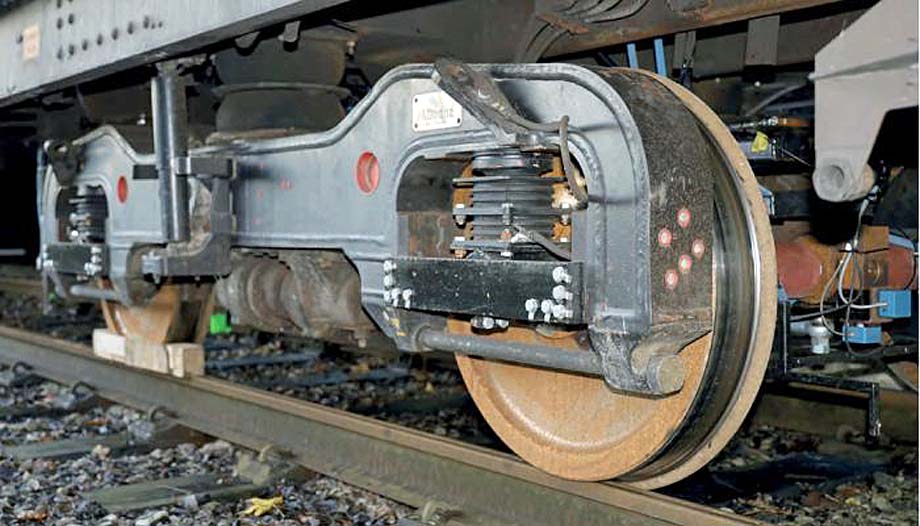
Looking at the standard arrangement since railways began, of a wheel fixed to each end of an axle, when going around a curve something has to slip, and that brings stress and wear.
Just like a runner on the outside lane has to run further around a bend than one on the inside, the wheel on the outside of the curve has to go further than the one on the inside.
One of the clever things we take for granted is how railway wheels cope with this, which is the wheel tread profile.
Being basically a cone shape, this allows the wheel to move sideways so one wheel can run on the smaller diameter bit of the cone, the other on the larger diameter, so that second one goes further than the smaller one per revolution.
Many engineers have been kept amused for nearly two centuries fiddling about with this basic arrangement, trying to prevent the wheel flange having to contact the rail, the last resort in keeping it on the track.
But the wheel flange does contact the rail on sharper curves when the basic conical guidance doesn't work.
Also, if you have a simple cone with no restraint, it will bounce about from side to side as it over-corrects if left to its own devices.
This is called "hunting" and must have shortened the fatigue life of many a first generation DMU and the track they ran on.
I've had many trips to Derby on Class 120 DMUs where anywhere over 50 mph you were slammed from side to side.
Last week I went on a Class 350/2, possibly the best riding modern rail vehicle, as smooth as silk, wonderful.
But this is achieved with a big, heavy, outside framed bogie with really stiff suspension, and Network Rail doesn't like that as it wears the track.
There's no pleasing some people.
Speed Kills
As a rule, the faster you want to go the stiffer the bogie has to be, because it has more energy to deal with.
You really don't want to start hunting at 140 mph, as you will soon become acquainted with local farmland.
I use the phrase "want to go" because British Rail and the Department for Transport had/has a habit of specifying trains to be capable of going faster than they actually will go, just in case.
This happened with the Mk 4 on BR, the Intercity Express Train from the DfT, and is now happening with the HS2 rolling stock.
High-speed means stiff suspension, which when it goes on to ordinary track gives a bad ride.
I share the guilt for specifying Class 458s for 100 mph on the basis that they would be more flexible, but as it turned out they rarely exceed 75, so their bogies could have been less stiff.
The way around this is to use a HALL bush, which allows slow movement on curves, but the oil inside it prevents the rapid movement of hunting.
There is now a HALL 2.0 which moves from passive restraint to active steering of the wheelset, although the wheels still rotate together on the axle.
Trying not to digress too much, Network Rail also gets sniffy about axle loads, and has convinced people that anything over 20 tonnes causes a big increase in damage.
Consequently, there has been a rush to inside frame bogies because they are lighter and ride doesn't matter anymore since we don't have a spreadsheet box for comfort.
Having said that, putting inside frame bogies on the new sleeping cars is just criminal negligence in my book.

Tread Carefully
It has been known since Advanced Passenger Train days, and probably earlier, that if you could steer the wheelset more accurately than the wheel profile can, you will reduce wear on the wheel and the rail.
There are two problems with the business case to do this, which is that the wheel and rail belong to two different people, and the fact that it isn't usually worth the trouble.
Network Rail sets a track access charge for every new train, which is arrived at in a fiendishly complicated way, including the company's favourite axle load measure, and a measure related to how stiff the bogie is.
This is where I have to try not to put you off so you page-hop to Alan Williams.
Suffice to say that track access charges are not much in the grand scheme of things, although softening the suspension on the "track lathe" Class 185s cut their bill from £5.5 million to £4 million per year.
See, barely one director's salary.
As for the wheels, they dominate rolling stock maintenance costs now that brake pads have most of their work done by regenerative braking or retarders.
Unsurprisingly, millions have been spent on optimising wheel re-profiling to extend wheel life.
We can make them out of harder steel, but that just transfers the issue to the track, and Network Rail tends to notice, eventually.
As an ex-Pacer engineer, I was more than familiar with wheel wear, which advertises itself with squealing and disappearing wheel treads.
Pacer wheels have a life of about 200,000 miles, compared to a Sprinter of 400,000.
This costs the same as there are half as many wheels on a Pacer, but clever new stock can get million mile wheelsets.
I could never justify the cost of steering wheelsets on Pacers, so on the main line that is up to five times harder.
So, what has this D stock vehicle got that makes it worthy of your valuable time?
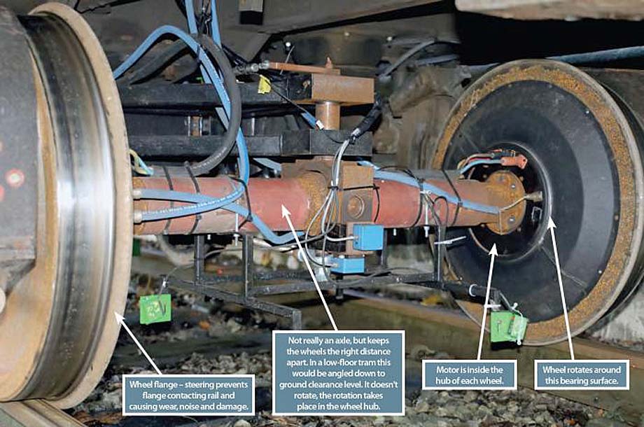
Motors built into the wheel hub which steer the wheels by powering them at different speeds.
Sounds easy doesn't it, but it isn't.
It is called the "ActiWheel Guided Traction System" and works a bit like a tank, which steers by one track going faster than the other.
Running the motor on the outside of the curve slightly faster than the one on the inside means you don't need a load of hefty kit shoving the wheelset about.

Entry Level Metallurgy
After discussing how hard it is to justify adding this sort of kit, SET plays its Joker, RCF, Rolling Contact Fatigue, or gauge corner cracking, which most of us had never heard of until the Hatfield accident.
The forces generated in the wheel-rail interface described above, along with those from traction and braking, stretch out the rail head, causing little cracks.
Metallurgy ideally needs a degree, but here you can make do with a paper clip.
Bend it a bit and it springs back, that's how it works, do that as much as you like and you still have a paper clip, that's elastic deformation.
Bend it a lot and it stays bent, which is plastic deformation, and you now need a new paper clip.
Keep on bending it backwards and forwards and that is "work hardening" leading to plastic fracture.
You now have two tools for getting SD cards out of iPhones, but you definitely need a new paper clip.
The rail head is steel, just a bit bigger, so if it gets too much stretching it cracks, showing up as lots of little lines on the rail head.
We can live with these, but they have the effect of raising the stress in the material underneath them, and if they get deep enough, the effect is like the little nick in a Kit-Kat wrapper, a bit of force and it rips apart.
Opposing Forces
Network Rail apparently spends about £250 million per year managing or rectifying RCF, so preventing it now looks a better bet.
Rail grinding removes the RCF, but at the expense of rail life, just like wheel re-profiling reduces wheel life.
Obviously, rail replacement is big money, but to prevent it you would have to fit all the trains on a route with this equipment, and it isn't a mod, we are talking at least new bogies.
Traction and braking forces remain, which also stretch the rail head as it provides the reaction to the forces of movement.
This is why Network Rail doesn't like locos and prefers lots of weedy motors.
The idea is certainly exciting and will reduce the track forces (called T-Gamma in the trade) which cause so much trouble.
SET claims it will save 5–10 percent of energy in the drive train, but I don't buy that.
As a rule, if you go under an EMU (in a depot that is), the bits that waste energy are the hot bits, and by far the hottest is the traction converter, so even if your motors are 100 percent efficient that is not 10 percent of the losses.
It will reduce rolling resistance, but again this is not a big number compared to other forces trying to stop the train such as air resistance, mass, and the Office of Rail and Road.
Low rolling resistance is what railways are all about, call in my defence a "Black 5" restarting a 10 coach train on the triangle at Blackburn.
Or pinch-barring wagons around the yard at Radyr, the hard part being stopping them again.
Oops.
However, on RCF plus a bit of energy saving there may be a business case, I'm just saying it isn't easy to make.
Now what has tight curves and needs a motor on every wheel?

Tram Revolution
I've said it before, but tram systems seem to be bought like model railway sets, where you always have a load of tight 90 degree bends to use up.
The squealing sound trams make going around these curves is the sound of £50 notes being shredded.
They also tend to be in city centres to dodge buildings, meaning they are the most expensive and disruptive places to replace rails.
Trams already use "stub axle" motors to allow a low floor where the axle would be, so using these hub motors solves two problems at once.
The ability to steer individual wheelsets to exactly the right place on the rail, and never come into flange contact would surely pay for itself, especially on a new fleet.
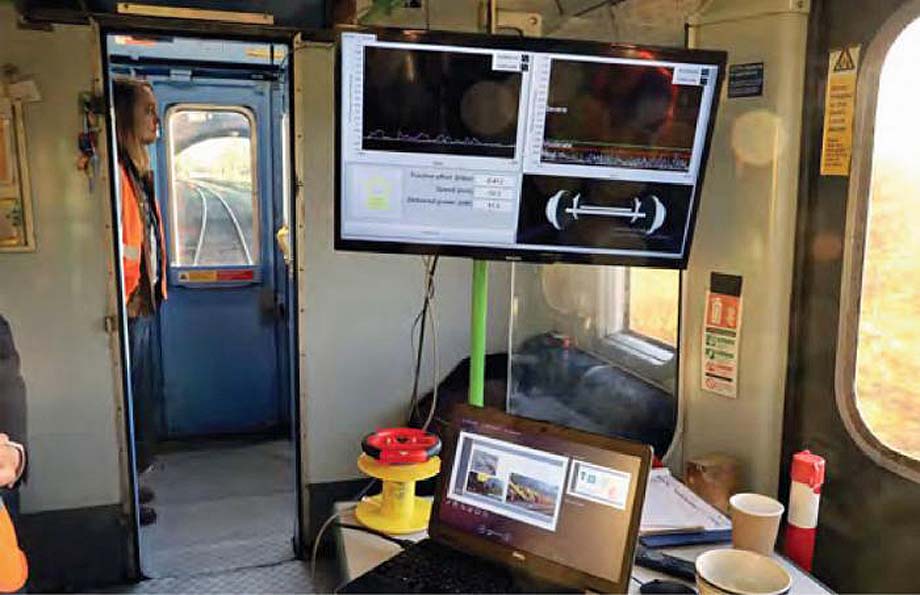
Talking of steering, there is a little steering wheel on the test unit which allows you to deliberately steer the wheel away from the narrow way, then you can watch it quickly return when the machine takes control again.
Switch it off and it wanders about at will.
If you see a rail where wheels are superbly controlled by us rolling stock engineers you will notice only a thin line on the rail head is shiny, so with this system might an even narrower line upset those hard-to-please track people?
Well, if it did you could programme the system to move about a bit, just like we deliberately stagger the overhead wire to avoid wearing a groove in the pantograph head.
Unsprung Mass No Brakes
Something else track people don't like (they do go on, don't they?) is unsprung mass.
Pretty obviously this is how much metalwork wallops the track at every joint or bump, but which doesn't have the blow softened by springs.
Back in BR days when researchers were researchers and not benefit scroungers, they invented the Tubular Axle Induction Motor.
This was an inside-out motor built around the axle, and so not needing a gearbox, or a commutator.
The APT's hydrokinetic brake similarly sat inside a tube around the axle, containing a turbine that braked the train, the resulting heat being generated in the turbine when filled with water.
Both ideas of rolling stock genius foundered in part because they had high unsprung mass.
Thanks to further advancement in motor technology the motors on this train fit in a resilient mounting in the wheel hub and are only 50-60 mm thick.
There is only 40 kilograms on each wheel, since there is no axle, no gearbox, and no brake disc (the latter being really heavy).
Thanks to the precision control of the motors there is no need for friction brakes, they can regenerate right down to standstill.
Conventional regenerative braking switches off in times of low adhesion, but in this case each wheel knows exactly what speed it should be doing and can control this using 16,000 sensor points per revolution.
Brave New World
By now you have considerably more expertise than the norm, and you can see the fantastic savings from wear, the energy wasted in producing that wear, the costs of putting it right, and the risks of getting it wrong.
But if we imagine a route where all the trains (or trams) are equipped with this kit, there are other things which come to mind.
There need be no track lubricators, and none of the adhesion loss, mess, and maintenance that goes with them.
No need for check rails on switches or curves, no air system or pneumatic brake control systems on the vehicles.
The emergency brake is simply to short out the connections, known as a "spoon brake", because they used one to short the connections.
This is real innovation, so how long before we can expect to see a production version?
SET estimates four years, and to be fair there is probably as much paperwork as metalwork involved in that.
I would expect any new tram system or fleet to look at this very carefully, as it would be nice to think the UK could lead this revolution.
Like second marriages, that is the triumph of hope over experience.
But here I am out of space and I haven't told you exactly how it steers the wheel so accurately.
Well, I've seen it steer (it is on YouTube as well), I've seen the lasers and counted at least 10 sensors.
What it does is (redacted).
Pan down.
Author unknown.
(likely no image with original article)
(usually because it's been seen before)
provisions in Section 29 of the
Canadian Copyright Modernization Act.

